16.68.050 Site development standards.
A. Free-standing wireless communication facilities shall conform to the following site development standards:
1. Support structures shall be set back from all residential property lines a distance equal to the height of the support structure plus the height of any antennas, and shall comply with all required setbacks of the zoning district in which it is located.
2. Support structures shall be designed and placed on the site in a manner that takes maximum advantage of existing trees, mature vegetation, and structures so as to:
a. Use existing site features to screen as much of the total WCF as possible from prevalent views; and/or
b. Use existing site features as a background so that the total WCF blends into the background with increased sight distances.
3. Relocation of a proposed facility on the site and infill landscaping of mature plant materials consistent with landscaping of the city may be required by the city to make the best use of or to supplement existing trees and vegetation to more effectively screen the facility.
4. Support structures, panel and parabolic antennas, and any associated hardware shall be painted a nonreflective color or color scheme appropriate to the background against which the WCF would be viewed from a majority of points within its viewshed. Natural colors only may be employed and the final colors and color scheme must meet the approval of the city.
5. Equipment enclosures shall conform to the following:
a. Equipment enclosures will be placed underground if site conditions permit and if technically feasible.
b. Equipment enclosures shall be screened from view except as provided in subsection (A)(5)(c) of this section.
c. Walk-in equipment enclosures:
(1) May not be constructed with exposed metal surfaces.
(2) May not be required to be totally screened from view provided the city finds that the walk-in equipment enclosure has been designed using materials, colors, and detailing that produces a structure which emulates the desired character of the zone in which it is located.
6. Security fencing, if used, shall conform to the following:
a. No fence shall exceed six feet in height.
b. Security fencing shall be effectively screened from view through the use of appropriate landscaping materials consistent with requirements of Chapter 16.80 LMC.
c. Chain-link fences shall be painted or coated with a non-reflective color.
B. The city shall consider the cumulative visual effects of WCFs mounted on existing structures and/or located on a given permitted site in determining whether additional permits can be granted so as to not adversely affect the character of the city.
C. Small cell wireless communications facilities shall conform to the following site development standards:
1. General Requirements.
a. All small cell WCFs in the ROW must follow City of Lacey Development Guidelines and Public Works Standards.
b. Ground mounted equipment in the rights of way is prohibited per Chapter 12.22 LMC, unless such facilities are placed underground or the applicant can demonstrate that pole mounted or undergrounded equipment is technically infeasible. If ground mounted equipment is necessary, then the applicant shall submit a concealment element plan.
c. No equipment shall be operated so as to produce noise exceeding requirements in LMC 16.57.030.
d. Small cell wireless communication facilities are not permitted on traffic signal poles.
e. Replacement poles and new poles shall comply with the Americans with Disabilities Act, city construction and sidewalk clearance standards, and state and federal regulations in order to provide a clear and safe passage within the rights of way.
f. If proposed antenna and equipment attachments to utility poles cannot meet structural standards set by the city for wind velocity and weight loads, carrier is required to provide a pole replacement before attaching antenna and equipment.
g. Applicant is required, where feasible, to place equipment on poles behind existing signs or banners already attached to poles to assist with camouflaging.
h. Per Puget Sound Energy’s requirements, all applicants must pay for their own electricity through flat-rate billing or metered use.
2. Small Cell WCFs Attached to Buildings.
a. Small cell WCFs may be mounted to the sides of a building if the antennas do not interrupt the building’s architectural theme.
b. The interruption of architectural lines or horizontal or vertical reveal is discouraged.
c. New architectural feature such as columns, pilasters, corbels, or other ornamentation that conceal antennas may be used if it complements the architecture of the existing building.
d. Small cell WCFs shall utilize the smallest mounting brackets necessary in order to provide the smallest offset from the building.
e. Skirts or shrouds shall be utilized on the sides and bottoms of antennas in order to conceal mounting hardware, create a cleaner appearance, and minimize the visual impact of the antennas. Exposed cabling/wiring is prohibited.
f. Small cell WCFs shall be painted and textured to match the building surfaces.
3. Small Cell WCFs Attached to Wooden Poles.
a. The wooden pole at the proposed location may be replaced with a taller pole for the purpose of accommodating a small cell facility; provided, that the replacement pole shall not exceed a height that is a maximum of ten percent taller than the existing pole.
b. A pole extender may be used instead of replacing an existing pole, but may not increase the height of the existing pole by more than ten percent. The pole extender shall be painted to approximately match the color of the pole and shall substantially match the diameter of the pole measured at the top of the pole.
c. Replacement wooden poles may either match the approximate color and materials of the replaced pole or shall be the standard new wooden pole used by the owner in the city.
d. Antennas, equipment enclosures, and all ancillary equipment, boxes and conduit shall be colored or painted to match the approximate color of the surface of the wooden pole on which they are attached.
e. Panel antennas shall be mounted as close to the surface of the wooden pole as practical.
f. Antennas should be placed in an effort to minimize visual clutter and obtrusiveness. Multiple antennas are not permitted.
g. A canister antenna may be mounted on top of an existing wooden pole, which may not exceed the height requirements described in subsection (C)(3)(a) of this section. A canister antenna mounted on the top of a wooden pole shall not exceed sixteen inches, measured at the top of the pole and shall be colored or painted to match the pole. The canister antenna must be placed to look as if it is an extension of the pole. In the alternative, the applicant may propose a side mounted canister antenna, so long as the inside edge of the antenna is no more than twelve inches from the surface of the wooden pole. All cables shall be concealed either within the canister antenna or within a sleeve between the antenna and the wooden pole.
h. An omni-directional antenna may be mounted on the top of an existing wooden pole, provided such an antenna is no more than four feet in height and is mounted directly on top of a pole or attached to a sleeve made to look like the exterior of the pole as close to the top of the pole as technically feasible. All cables shall be concealed within the sleeve between the bottom of the antenna and the mounting bracket.
i. All related cables and equipment shall be flush mounted to the surface of the pole, unless a further distance is technically required and is confirmed in writing by the pole owner.
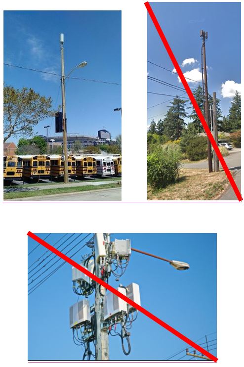
Figure 16.68.050(C)(3). Acceptable and unacceptable attachments
4. Small Cell WCFs Attached to Non-Wooden Poles.
a. A structural analysis is required to be submitted by applicant. If antennas and equipment to be attached to an existing non-wooden pole cannot meet load or wind requirements, the applicant is required to provide a replacement pole. See subsection (C)(4)(e) of this section.
b. Antennas and the associated equipment enclosures shall be sited and installed in a manner which minimizes the visual impact on the streetscape whether by fully concealing the antennas and associated equipment fully within the pole or through a concealment element plan which provides an equivalent or greater impact reduction. This requirement shall be applied in a manner which does not dictate the technology employed by the service provider nor unreasonably impair the technological performance of the equipment chosen by the service provider.
c. All conduit, cables, wires, and fiber must be routed internally in the light pole. Full concealment of all conduit, cables, wires and fiber is required within mounting brackets, shrouds, canisters or sleeves if attaching to exterior antennas or equipment.
d. An antenna on top of an existing pole may not extend more than six feet above the height of the existing pole and the diameter may not exceed sixteen inches, measured at the top of the pole, unless the applicant can demonstrate that more space is needed. The antennas shall be integrated into the pole design so that it appears as a continuation of the original pole, including colored or painted to match the pole, and shall be shrouded or screened to blend with the pole except for the canister antennas which shall not require screening. All cabling and mounting hardware/brackets from the bottom of the antenna to the top of the pole shall be fully concealed and integrated with the pole.
e. Any replacement pole shall substantially conform to the design of the pole it is replacing or the neighboring pole design standards utilized within the contiguous right of way.
f. The height of any replacement pole may not extend more than ten feet above the height of the existing pole or the minimum additional height necessary for adequate clearing from electrical wires, whichever is greater.
g. The diameter of a replacement pole shall comply with the city’s setback and sidewalk clearance requirements, ADA requirements, and, if a replacement light, then with the city’s lighting requirements.
h. The use of the pole for the siting of a small cell facility shall be considered secondary to the primary function of the pole. If the primary function of a pole serving as the host site for a small cell facility becomes unnecessary, the pole shall not be retained for the sole purpose of accommodating the small cell facility and the small cell facility and all associated equipment shall be removed.
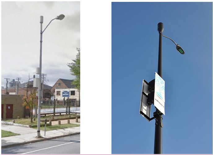
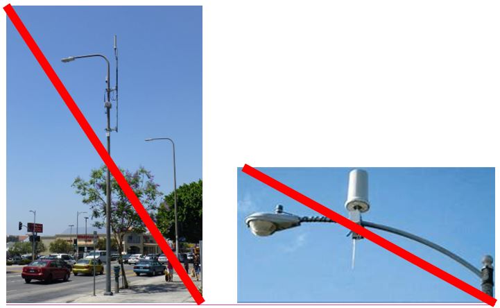
Figure 16.68.050(C)(4). Acceptable and unacceptable attachments
5. New Poles for Small Cell WCFs in the Rights of Way.
a. New poles within the rights of way are only permitted if the applicant can establish that:
(1) The proposed small cell facility cannot be located on an existing utility pole or light pole, electrical transmission tower or on a site outside of the public rights of way such as a public park, public property, building, or transmission tower.
(2) The new pole is no closer than two hundred fifty feet away radially from another privately-owned freestanding small cell.
(3) The proposed wireless communications facility receives approval for a concealment element design as follows:
(a) The concealment element design shall include the design of the screening, fencing, or other concealment technology for a tower, pole or equipment structure, and all related transmission equipment of facility associated with the proposed wireless communication facility, including but not limited to fiber and power connections.
(b) The concealment element design should seek to minimize the visual obtrusiveness of wireless communications facility installations. The proposed pole or structure should have similar designs to existing neighboring poles in the rights of way, including to the extent technically feasible similar height. Other concealment methods include, but are not limited to, integrating the installation with architectural features or building design components, utilization of coverings or concealment devices of similar material, color and texture – or the appearance thereof – as the surface against which the installation will be seen or on which it will be installed, landscape design, or other camouflage strategies appropriate for the type of installation. Applicants are required to utilize designs in which all conduit and wirelines are installed internally in the structure or otherwise integrated into the design of the structure.
(c) If the director has already approved a concealment element design either for the applicant or another wireless communications facility along the same public right of way or for the same pole type, then the applicant shall utilize a substantially similar concealment element design, unless it can show that such concealment element design is not physically or technologically feasible, or that such deployment would undermine the generally applicable design standards.
(d) Prior to the issuance of a permit to construct a new pole or ground mounted equipment in the right of way, the applicant must obtain a site-specific agreement from the city to locate such new pole or ground mounted equipment. This requirement also applies to replacement poles that are higher than the replaced pole, and the overall height of the replacement and the proposed wireless communication facility is more than fifty feet.
(e) These design standards are intended to be used solely for the purpose of concealment and siting. Nothing herein shall be interpreted or applied in a manner which dictates the use of a particular technology. When strict application of these requirements would unreasonably impair the function of the technology chosen by the applicant, alternative forms of concealment of deployment may be permitted which provide similar or greater concealment.
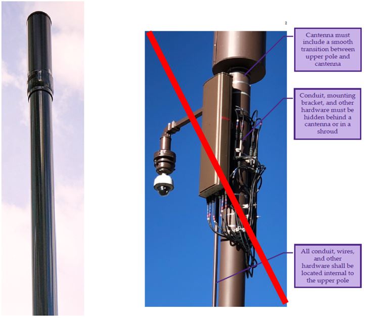
Figure 16.68.050(C)(5). Acceptable and unacceptable new poles
(Ord. 1546 §14, 2019; Ord. 1052 §1, 1997).